what are you looking for?

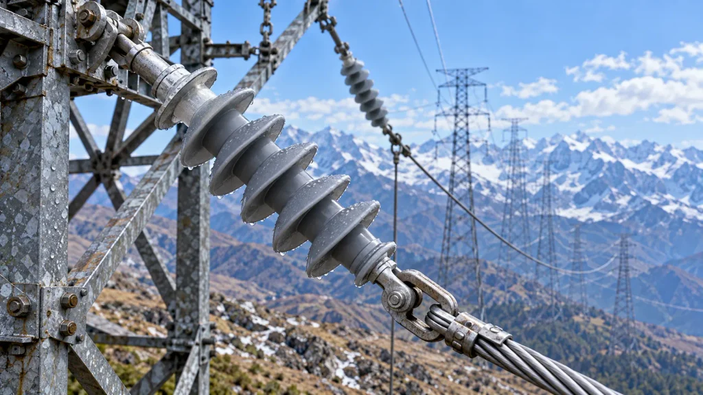
For a high-altitude transmission project, specify a composite insulator as part of the line’s complete insulation-coordination design, not by adding an arbitrary percentage to its length. The purchase specification should identify the route elevation and service conditions, required electrical withstand levels and clearances, pollution creepage duty, mechanical loads, fitting interfaces, and the evidence required for design approval. The applicable utility and project standards must determine any altitude correction or added external-insulation margin.
Record the minimum, typical, and maximum elevations across the line section or project area, then identify the highest elevation at which the equipment will operate. A single site elevation can hide significant route variation. State the basis and source for the elevation data, the design ambient conditions, and the utility’s applicable standards and editions. Ask the owner to confirm whether the project uses a prescribed altitude threshold or correction method; do not assume one applies universally.
The electrical design team should state the system’s nominal and maximum operating voltage, grounding arrangement, switching and lightning exposure, and required power-frequency, switching-impulse, and lightning-impulse withstand levels where applicable. Include the line’s insulation-coordination assumptions and the phase-to-phase, phase-to-ground, and structure clearances that constrain the assembly. These values belong to the project design basis; they should not be reverse-engineered from a generic insulator catalogue description.
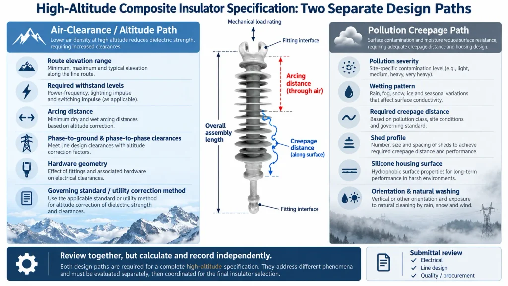
Reduced air density at elevation can affect the external insulation strength of air gaps. The relevant design questions include withstand performance, arcing distance, hardware geometry, and the clearances between energized parts and grounded structures. These are not interchangeable with the length of the silicone sheds. The engineer responsible for insulation coordination should apply the method required by the governing standard and utility specification, then document the resulting electrical requirements for the insulator string and surrounding line geometry.
Creepage distance addresses a different exposure: leakage paths along an insulator surface under pollution and wetting. Specify the pollution severity and the required creepage basis separately from altitude-related air-clearance considerations. Salt, industrial deposits, dust, fog, and rainfall can change the surface duty; a higher elevation alone does not define the pollution class. CECI’s composite-insulator creepage selection guide discusses how salt, dust, and humidity inform creepage selection, but project requirements still govern the final value.
Avoid writing ‘increase creepage for altitude’ as a substitute for electrical coordination. A project may need changes to external clearance, string length, fitting arrangement, or line geometry, while its creepage requirement follows the pollution assessment. The two design paths should be reviewed together, but calculated and recorded independently.
Name the required configuration: suspension, tension, line-post, or another defined arrangement. State the rated voltage class, number and arrangement of units where applicable, overall assembly length, dry arcing distance, creepage distance, shed profile or dimensional envelope, and terminal fitting type. For composite designs, identify the required fiberglass-reinforced polymer (FRP) core, silicone-rubber housing, and metal end fittings only to the level supported by the approved design and supplier documentation. The project may also need specified corona or grading hardware; do not assume it is included unless the drawings and bill of materials say so.
Confirm that the insulator’s dimensions fit the tower, conductor, jumper, and hardware geometry while preserving the clearances established by the insulation-coordination study. Where a supplier proposes an alternate length, shed profile, or fitting, require a marked-up drawing and a documented review of the electrical and mechanical consequences. CECI’s polymer insulator range can be used to identify product families for a technical enquiry; the listed family alone does not establish suitability for a particular high-altitude line.
Give the required specified mechanical load or other governing mechanical rating, the load direction, and the applicable load combinations. Explain how conductor tension, wind, ice where relevant, line angle, broken-wire cases, and installation or maintenance loads enter the project’s design. The rating must be checked against the actual line duty and the applicable safety factors; a catalogue load value is not a substitute for that calculation. Include the required fitting standard or drawing, connection dimensions, articulation needs, and compatibility with clamps, yoke plates, arcing hardware, and adjacent line fittings.
For the FRP core and end-fitting interface, request the supplier’s controlled drawing, material identification, sealing details, and applicable design or type-test documentation. For the silicone housing, define the required profile, material and color only where the approved project design calls for them. Ask how changes to materials, molds, process, or equipment are controlled. Build a first-article approval hold point into the quality plan and require revalidation after agreed changes to process, molds, materials, or equipment, consistent with the contract’s inspection and change-notification requirements.
A useful request for quotation gives every bidder the same inputs and identifies which values are fixed, calculated, or proposed by the supplier. Attach the insulation-coordination requirements, line arrangement, interface drawings, route elevation range, pollution basis, mechanical load cases, and applicable standards. Request deviations in a separate schedule rather than allowing assumptions to disappear in catalogue notes.
At minimum, ask the supplier to return: a completed datasheet; a dimensioned assembly drawing; electrical and mechanical ratings with their test basis; fitting and hardware details; material and sealing information; quality-control and traceability records required by contract; and a compliance/deviation list. Require the design authority to review proposed altitude-related adjustments against the project’s governing standard before release for manufacture.
CECI lists a 36 kV pin-type composite sleeve insulator described for high-altitude use. This is a product-specific example, not evidence that the same construction, voltage class, or configuration meets a transmission-line suspension or tension duty. Treat it as a starting point for a supplier discussion only, and request the exact configuration and ratings needed for the project.
Use a cross-discipline review before approving a proposed model. The electrical engineer should verify withstand levels, clearances, arcing distance, creepage, and any altitude treatment. The line-design engineer should confirm geometry, mechanical loads, and hardware interfaces. Quality and procurement should check traceability, test evidence, inspection points, change control, delivery scope, and exceptions to the specification.
A high-altitude label is not a substitute for a complete submittal. Confirm that the evidence applies to the exact design, rating, and interfaces being offered. If the route spans different elevations or pollution environments, verify whether one design covers the full duty or whether the line should be divided into design zones. Keep all accepted deviations and assumptions in the approved record so they remain visible during manufacturing and commissioning.
Specify high-altitude composite insulators through the project design basis: elevation range, insulation-coordination requirements, external clearances, pollution creepage, mechanical loads, dimensions, fittings, verification evidence, and change control. Do not rely on a generic altitude multiplier or treat creepage and air clearance as the same problem. A complete, reviewed datasheet lets EPC contractors compare bids on the same technical basis and reduces the risk of approving a product whose documented duty does not match the line.
Not automatically. The required assembly and clearances depend on the project insulation-coordination study, governing standards, utility criteria, and line geometry. The design authority should determine whether length, hardware, or structure clearances need adjustment.
No. Creepage is measured along the insulating surface and is primarily selected for pollution and wetting duty. Arcing distance and air clearances relate to external electrical withstand. Specify and verify both where required.
Include route elevation, system voltage and withstand requirements, pollution basis, mechanical load cases, configuration, dimensions, interface drawings, applicable standards, required test and quality records, and a format for listing deviations.
No. Confirm that the designation and supporting evidence apply to the exact voltage class, insulator type, mechanical duty, fittings, and service conditions in the project specification.
For a project fit check, send the model or configuration, route elevation range, system voltage, mechanical duty, pollution conditions, interface drawing, and quantity to CECI’s technical team.

 Room 1502, NO.12, Shangwu Waihuan Road, CBD, Zhengzhou, China
 +86-18937178812
 sales@gridinsulators.com


 November 5, 2026
