what are you looking for?

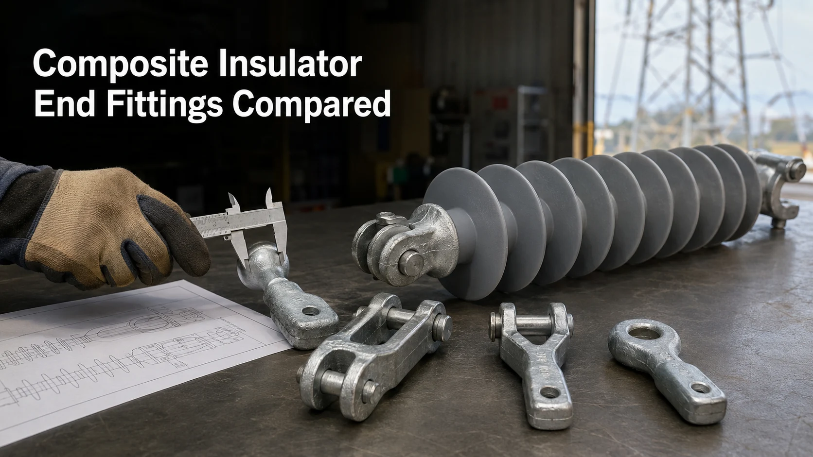
Selecting composite insulator end fittings is not simply a matter of choosing a familiar connection name. The fitting must match the adjacent line hardware, mechanical load requirements, interface dimensions, installation method, and operating environment. A ball fitting cannot be ordered without confirming its corresponding socket, and a clevis cannot be selected without checking the tongue, pin, and opening dimensions.
For engineers and procurement teams, the practical objective is to identify a coupling system that can be assembled without modification, transfer the specified load, and support future maintenance or replacement. This guide compares the major connection types and explains what information should be confirmed before issuing an RFQ.
Composite insulator end fittings connect the load-bearing core of the insulator to tower hardware, conductor-side fittings, clamps, or other components in the insulator string. An incorrect interface can delay installation even when the insulator’s voltage class and mechanical rating appear suitable.
Compatibility problems commonly arise when a buyer specifies only a general name such as “ball fitting” or “clevis end.” That description does not define the mating size, pin diameter, orientation, connection mark, or critical dimensions. Terminology can also vary among drawings, suppliers, and regional practices.
The selection should therefore start with the complete assembly. Review the tower-side connection, conductor-side hardware, insulator position, expected load direction, available articulation, and installation clearances. Buyers planning a complete overhead-line package can use the high-voltage insulators and power grid hardware overview to identify the related product groups that may need to be coordinated.
The following table provides a practical comparison. It should be used as an initial selection tool rather than a substitute for approved drawings and project specifications.
| Coupling type | Typical connection logic | Main selection advantage | Critical checks before purchase |
|---|---|---|---|
| Ball and socket | A ball end engages a corresponding socket fitting | Allows articulation and is common in suspended or tension assemblies | Ball and socket size, connection mark, locking arrangement, load rating and mating hardware |
| Clevis and tongue | A tongue fits between clevis arms and is secured by a pin | Provides a direct pinned connection with controlled orientation | Clevis opening, tongue thickness, pin diameter, hole size, width and installation clearance |
| Y-clevis | A forked or Y-shaped end connects through a pin to compatible hardware | Useful where the assembly requires a defined forked interface | Fork geometry, pin dimensions, orientation, connected fitting and load direction |
| Eye end | An eye receives a pin, bolt, shackle, or compatible connecting component | Offers a simple connection point for selected line-hardware arrangements | Eye diameter, section dimensions, mating pin, movement requirements and bearing contact |
The composite insulator end fitting product range includes multiple connection forms. However, the presence of the correct fitting name does not confirm interchangeability. The dimensions and mechanical requirements of each project still need to be checked.
A ball-and-socket connection is selected as a matched interface. The ball provides the rounded connecting end, while the socket receives it and is normally retained by a locking device appropriate to the assembly. This arrangement can accommodate angular movement, making it useful where the insulator string must articulate during installation or service.
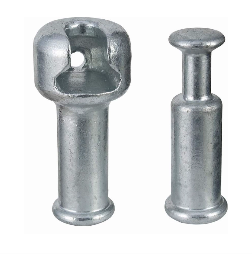
The primary procurement risk is assuming that every ball fits every socket. Buyers should confirm the applicable connection size or mark, dimensional drawing, locking arrangement, mechanical rating, and compatibility with existing string hardware. If the fitting is intended for replacement work, measurements from a worn component alone may be misleading. The original drawing, an undamaged sample, or verified dimensions from the mating hardware provides a more reliable reference.
Ball-and-socket fittings are unsuitable when the connected hardware requires a fixed clevis interface or when the available clearances do not permit the expected movement. The connection type should not be changed merely because a different fitting is readily available.
A clevis-and-tongue assembly uses a pin to connect a tongue between two clevis arms. It offers a straightforward mechanical connection, but several dimensions must align simultaneously. These include the clevis opening, tongue thickness, pin diameter, hole diameter, edge clearance, and the orientation of the two components.
This connection is appropriate when the adjoining hardware already uses a compatible pinned interface and when the assembly requires controlled alignment. It is not appropriate if the tongue is too thick for the opening, the pin does not match the hole, or the connected parts cannot rotate or align as required.
A frequent purchasing error is specifying the load rating without providing an interface drawing. Two fittings may have a similar nominal mechanical classification but different connecting dimensions. Procurement documents should identify both ends of the insulator because tower-side and conductor-side connections may differ.
A Y-clevis provides a forked connection that is secured by a pin to compatible hardware. It may be chosen when the line assembly requires that particular geometry or orientation. Buyers should confirm the fork width, pin size, hole dimensions, overall orientation, and available installation space. A Y-clevis should not be treated as interchangeable with every conventional clevis simply because both use a pin.
An eye end provides an opening for a mating pin, bolt, shackle, or other specified connector. It can be practical in assemblies built around an eye connection, but the eye diameter alone is insufficient for selection. The buyer should also verify section dimensions, bearing contact, connected hardware, movement requirements, and load direction.
For both types, the approved assembly drawing should control the purchasing decision. Photographs can help identify the general configuration, but they cannot reliably establish tolerances or hidden dimensions.
Selection should proceed from the complete interface toward the insulator rather than from a product photograph. First identify what connects to each end: tower hardware, a yoke plate, a socket, a clevis, a shackle, a conductor clamp assembly, or another component.
Next, record the connection type and all relevant dimensions. For pinned joints, this normally includes pin diameter, opening width, tongue thickness, hole size, and orientation. For ball-and-socket systems, confirm the matched interface designation and retaining arrangement. If the replacement must fit an existing installation, provide both the original part drawing and dimensions of the undamaged mating component.
A connection should not be selected solely because it can be physically assembled. The interface must also support the specified mechanical duty and required movement without unintended interference or unfavorable loading.
The end fitting forms part of the insulator’s mechanical load path. Procurement teams should state the required mechanical rating and clarify whether it applies to an individual fitting, a complete insulator, or another assembly. The applicable test and acceptance requirements should be identified in the project specification rather than inferred from a catalog title.
Material, manufacturing route, finish, and corrosion protection should be verified against the application. Requirements may vary with the environment, connected materials, maintenance expectations, and project standards. A fitting used in a coastal, industrial, or highly humid environment may require different corrosion considerations from one installed under less aggressive conditions.
Buyers should also confirm whether grading or corona-control components are required for the complete insulator configuration. These decisions depend on system voltage, geometry, project design, and the product specification.
Before ordering a replacement end fitting, determine whether the component is designed to be replaced separately in the relevant assembly. Composite insulator end fittings are connected to the load-bearing core through a controlled manufacturing process. Field removal or substitution should not be assumed to be acceptable.
If there is cracking, deformation, corrosion, seal deterioration, housing damage, exposed core material, uncertain attachment integrity, or an unknown failure cause, the complete insulator should be assessed by qualified personnel. Where the original interface cannot be verified, sourcing complete polymer composite insulators may be more appropriate than attempting to adapt an unmatched fitting.
For replacement procurement, submit the original model, drawings, clear photographs, installation position, operating environment, required quantity, known failure symptoms, and dimensions of the connected hardware. This allows the supplier to evaluate whether an existing product is suitable or whether additional engineering confirmation is needed.
Common sourcing mistakes include matching by appearance, relying only on voltage class, confusing working requirements with mechanical ratings, and changing the end connection without reviewing adjacent hardware. Another risk is ordering one end correctly while leaving the opposite end undefined.
Do not enlarge holes, grind tongues, spread clevis arms, substitute pins, or add improvised adapters to make incompatible parts fit unless the modification has been formally engineered and approved. Such changes can affect clearances, contact areas, load transfer, corrosion protection, and maintenance practices.
A broader power line hardware fittings sourcing guide can support procurement teams that also need to coordinate clamps, links, shackles, yoke plates, and related hardware rather than purchasing the insulator end fitting in isolation.
A useful RFQ should reduce interpretation. At minimum, include:
A qualified supplier should review whether the selected connection matches the stated assembly rather than responding only to a generic product name. Buyers should request product-specific drawings and confirm which dimensions, accessories, and documentation are included in the quotation.
CECI publicly lists ball-socket, tongue-clevis, Y-clevis, and eye-end products within its overhead-line hardware range. Because available configurations may vary by load, size, material, and application, the quoted item should still be checked against the buyer’s drawings and mating hardware. Project teams can contact CECI with specifications, drawings, quantities, application details, samples, or replacement photographs for product matching and quotation review.
The correct composite insulator end fitting is the one that matches the complete mechanical interface—not merely the connection name. Ball-and-socket systems provide an articulated matched coupling, clevis-and-tongue arrangements provide a pinned connection, and Y-clevis or eye ends serve assemblies designed around their specific geometry.
Before purchasing, verify the interfaces at both ends, dimensional drawings, mechanical requirements, materials, finish, environment, accessories, and connected line hardware. A detailed RFQ gives CECI a stronger basis for evaluating available configurations and identifying information that still requires engineering confirmation.
Not automatically. The ball and socket must use compatible interface dimensions or connection designations, and the locking arrangement, load requirement, and connected hardware must also match. Verify the project drawing and mating component before ordering.
Confirm the clevis opening, tongue thickness, pin diameter, hole diameter, component width, orientation, and relevant overall dimensions. The required mechanical rating and mating hardware should accompany these measurements.
Only if the complete connection has been reviewed and approved for the new interface. An eye and a clevis use different mating arrangements, so changing the fitting may require different hardware and may affect movement, clearances, and load transfer.
Start with the general connection form, then collect measurements, photographs from several angles, the insulator model, installation position, and details of the mating hardware. An original drawing or undamaged sample is more reliable than appearance alone.
Send drawings, interface dimensions, mechanical requirements, materials or finish requirements, operating environment, connected hardware, target quantity, and required accessories. For replacements, also provide the original model, photographs, samples, and any observed damage.

 Room 1502, NO.12, Shangwu Waihuan Road, CBD, Zhengzhou, China
 +86-18937178812
 sales@gridinsulators.com


 October 22, 2026