what are you looking for?

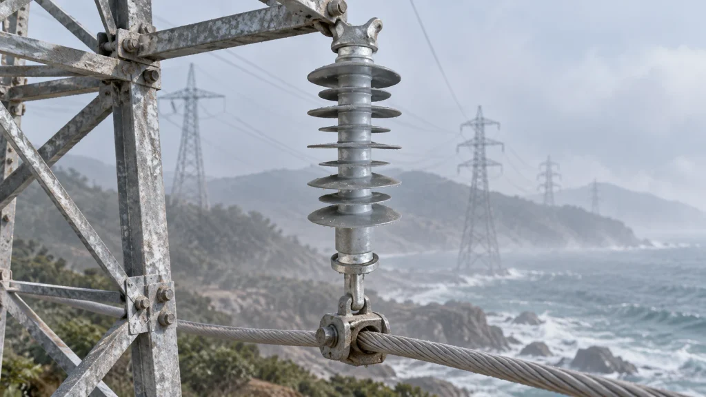
For a composite insulator exposed to salt, dust, or persistent humidity, creepage distance should be specified as part of a complete insulation design. The required surface path depends on voltage, pollution severity, wetting, shed geometry, natural cleaning, installation position, and the project standard. A longer catalog length alone does not prove that an insulator will perform correctly. This guide shows engineers and procurement teams what to define, check, and approve before ordering.
Creepage distance is the path measured along the insulating surface between conductive parts. When salt, dust, or industrial contamination becomes wet, the surface can support leakage current and dry-band activity. Humidity can keep deposits damp for longer, while low rainfall may reduce natural cleaning. The risk is therefore controlled by the relationship between the deposit, the water film, the surface profile, and the available leakage path.
A composite insulator normally combines a fiberglass or FRP core rod, silicone rubber sheds, and metal end fittings. Its silicone surface may provide hydrophobic behavior, but hydrophobicity does not replace a correctly specified creepage distance. The RFQ should make the environmental assumptions visible so the supplier can verify the selected configuration instead of substituting a familiar length or voltage label.
Start with the site description. Record whether contamination comes from sea spray, salt fog, road dust, cement or mining particles, agricultural emissions, industrial pollution, or a combination. Describe how often the surface becomes wet through fog, dew, rain, condensation, or washing. Include shoreline exposure, wind direction, rainfall pattern, altitude, temperature, UV exposure, and access for inspection or cleaning.
Do not convert the word “coastal” directly into a universal creepage number. The same shoreline distance can produce different wetting and deposition patterns because of terrain, wind, rainfall, shielding, and maintenance access. Put the conditions in the specification and require the final value to be verified against the applicable design method.
The RFQ should state the required creepage distance, the reference drawing, the tolerance, and the measurement method. Clarify whether the value is a total surface path, a protected or profile-dependent path, or another project-defined characteristic. This avoids comparing unlike values from different suppliers.
Creepage should be reviewed with rated voltage and pollution assumptions. Ask the supplier to show how the specified value is created by the shed diameter, shed spacing, alternating profile, and overall length. If the project uses a named standard or utility practice, cite it in the RFQ and identify any correction or selection factors that the design authority must approve.
Keep arcing distance or air clearance as a separate controlled dimension. A product can have a long surface path but still fail a clearance, phase spacing, or hardware-interface requirement. The released drawing should show both dimensions and their tolerances, along with core rod diameter, end-fitting position, and any required grading hardware.
Shed geometry determines how deposits collect, how water drains, and how much of the surface is naturally washed. Specify shed diameter, spacing, overhang, profile, and the relationship between protected and exposed surfaces when those features affect the design. A profile that retains a continuous wet film may not deliver the same pollution performance as a profile that sheds water and limits bridging.
For silicone rubber housings, define the material and the evidence required for weathering, UV exposure, surface condition, and hydrophobic performance. Acceptance should cover cuts, tears, voids, flash, contamination, incomplete molding, and damage at the interface with the metal fittings. Hydrophobicity can change with aging, contamination, and surface condition, so the RFQ should state how the characteristic will be evaluated for the approved product configuration.
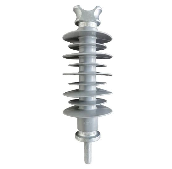
The CECI polymer insulators category can be reviewed when the project needs a composite construction with a fiberglass core, silicone rubber sheds, and metal end fittings.
Salt and humidity do not remove mechanical requirements. Include mechanical failing load, bending or tensile duty where relevant, wind and conductor loading assumptions, and the insulator position. Check that the selected overall length and shed dimensions do not change phase clearance, tower geometry, or adjacent hardware.
The end fittings are part of the insulation assembly and the load path. Specify the coupling type, pin or hole dimensions, orientation, material, surface treatment, and mating hardware. Suspension clamps, tension fittings, yoke plates, arcing horns, brackets, and connectors should be identified on the same drawing or interface schedule.
For a product-level reference, see the 33kV 70kN silicone rubber composite suspension polymer insulator page and confirm the project-specific dimensions before approval.
A useful composite insulator specification lets a supplier respond field by field. Attach the line or assembly drawing and make the following items mandatory in the technical offer:
This format makes it easier to compare a technical response with the approved design. It also reduces the risk of receiving a similar-looking insulator that has a different surface path, fitting interface, or mechanical rating.
Before mass production, inspect a first article against the released drawing and specification. Review material identity, core and housing condition, shed geometry, creepage and arcing dimensions, end-fitting interface, visual quality, and the agreed inspection records. The acceptance limits should be the actual project criteria, not an informal visual comparison with a catalog image.
Keep the approved configuration under change control. A change to materials, molds, equipment, tooling, fittings, or process conditions may affect conformity and may require re-validation. CECI’s quality information states that first-article inspection is conducted before each batch and that production begins after approval. That process is useful only when the released drawing, records, and change triggers are clearly defined.
CECI China Energy and Chemical Industry Co., Ltd. identifies composite and polymer insulators for transmission, distribution, substation, railway, industrial, coastal, salt-fog, high-humidity, and polluted applications. The product information covers FRP or fiberglass core rods, silicone rubber sheds, metal end fittings, rated voltage, mechanical failing load, creepage distance, arcing distance, shed dimensions, core rod diameter, fitting type, and standards requirements. Final selection remains dependent on the project voltage, pollution conditions, installation position, mechanical duty, and approved drawing.
For a fit check, send the location and contamination description, voltage, required creepage and arcing distances, mechanical load, shed profile, core and fitting dimensions, quantity, and documentation expectations. For related line hardware, review CECI’s Overhead Line Hardware Fittings and Accessories scope so the insulator and its mating parts are evaluated as one assembly.
A defensible creepage specification connects site contamination to surface path, shed profile, hydrophobicity, arcing distance, mechanical duty, and fittings. It names the measurement basis, keeps universal numbers out of the RFQ unless the governing design method supports them, and protects the approved configuration through first-article inspection and change control. For a project-specific review, contact the CECI technical team with the drawing, voltage, pollution conditions, mechanical load, and required records.
No. The required path must be evaluated with shed profile, wetting, natural cleaning, voltage, installation position, and the applicable project method. A longer catalog dimension does not replace system verification.
No. Hydrophobic behavior and creepage distance address related but different parts of pollution performance. Both should be controlled for the approved material and configuration.
Creepage is measured along the insulating surface. Arcing distance or clearance is the shortest relevant air path. Both dimensions can affect insulation coordination and must be specified separately.
Re-validation may be needed after changes to materials, molds, equipment, tooling, fittings, or process conditions. The required scope should follow the project change-control plan.

 Room 1502, NO.12, Shangwu Waihuan Road, CBD, Zhengzhou, China
 +86-18937178812
 sales@gridinsulators.com


 October 15, 2026