what are you looking for?

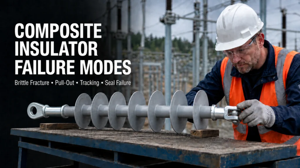
Composite insulator failure modes can look similar during a routine line inspection, yet they may involve very different mechanical and electrical risks. A burned housing does not automatically mean tracking, and a damaged FRP core is not necessarily a brittle fracture. Engineers and maintenance teams must identify the likely failure path before deciding whether to monitor, investigate, or replace the unit. For replacement buyers, the same evidence should be converted into clear specifications covering the application, mechanical rating, insulation requirements, end fittings, dimensions, and operating environment.
The first step in composite insulator failure analysis is to locate the damage. Surface deterioration, an abnormal end fitting, an exposed core rod, and a damaged end seal point toward different inspection priorities.
| Failure mode | Typical location | Possible warning signs | Main hidden risk | Practical next step |
| Brittle fracture | FRP core rod | Partial rod fracture, exposed fibers, damaged housing near the fracture | Loss of mechanical load-bearing capacity | Arrange an engineering assessment and investigate possible moisture or chemical ingress |
| Pull-out | Rod–end fitting interface | Rod displacement, fitting separation, abnormal interface position | Inadequate load transfer between the rod and fitting | Remove or secure the unit according to the asset owner’s procedure and inspect similar units |
| Tracking and erosion | Silicone rubber housing | Conductive-looking tracks, erosion, burning, or localized surface loss | Continued surface discharge and possible exposure of internal components | Assess damage depth, contamination, wetting conditions, and electrical activity |
| Seal failure | Housing–end fitting junction | Cracks, gaps, separation, corrosion indicators, or moisture evidence | Water reaching the core rod or bonded interface | Investigate the seal and internal condition before selecting a replacement |
These signs support preliminary classification, not a final root-cause conclusion. CIGRE condition-assessment guidance notes that external observations alone may not reveal every internal defect. Inspection findings should therefore be considered together with operating history, environmental exposure, electrical activity, and suitable online or offline tests.
Polymer insulator failure usually develops through a combination of material condition, electrical stress, mechanical loading, interface quality, and environmental exposure. Understanding how these factors interact helps maintenance teams avoid treating every visible defect as the same problem.
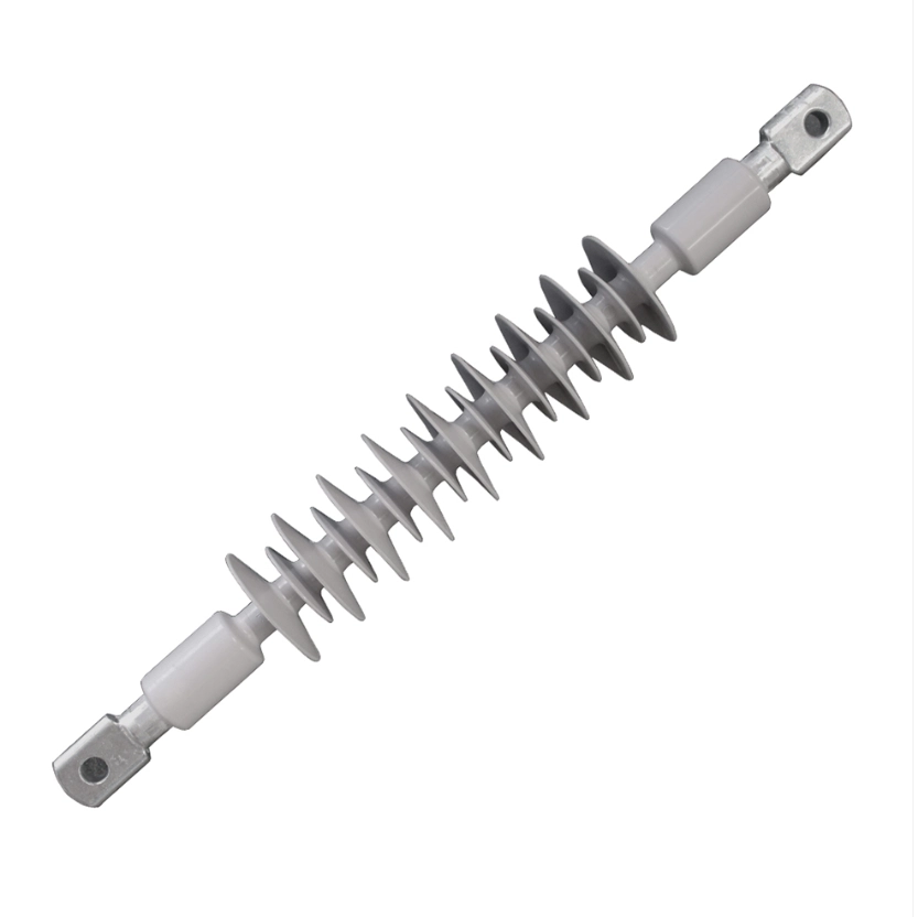
Composite insulator brittle fracture affects the load-bearing FRP core rod. It is associated with a specific fracture process involving tensile stress and a chemically aggressive environment reaching vulnerable glass fibers. Moisture ingress, housing damage, or a compromised end seal may contribute to the failure path, but their presence does not by itself prove brittle fracture.
The fracture surface, location, surrounding housing, operating load, and evidence of contamination or moisture should be examined. A visibly broken rod requires urgent engineering attention because mechanical integrity may already be compromised. Less obvious internal core damage may not be detected through routine visual inspection, so an apparently intact housing should not be treated as conclusive evidence of a healthy rod.
Composite insulator pull-out failure occurs when the FRP rod separates or slips from the metal end fitting instead of transferring the specified mechanical load through the complete assembly. It must be distinguished from a broken fitting, a fractured rod, or damage caused after the insulator has already fallen.
Possible contributing factors include an unsuitable crimping process, dimensional mismatch, interface damage, incorrect load assumptions, or a product configuration that does not match the application. Investigators should compare the failed interface with drawings, fitting dimensions, mechanical requirements, and similar units in service. Buyers reviewing insulator end fittings for composite insulators should confirm the connection type, rated load, material, dimensions, surface treatment, and compatibility with the complete assembly.
Tracking and erosion affect the polymer housing but describe different forms of deterioration. Tracking creates a partially conductive surface path, while erosion involves progressive loss of housing material. Flashover marks, in contrast, may result from a discharge event without proving that a permanent conductive track has formed.
Wet contamination, poor surface condition, localized electrical stress, and unsuitable creepage performance may contribute to the problem. Inspectors should evaluate whether the mark is continuous, whether material has been lost, and whether the core or housing interface is exposed. Cleaning alone may be insufficient when discharge activity continues or erosion has reduced the protective housing. UV or infrared inspection may provide additional evidence, depending on the defect and operating condition.
The transition between the housing and metal end fitting is a critical inspection area. Cracks, separation, gaps, or interface damage may allow moisture to reach the rod, bonded surfaces, or fitting interface. The resulting deterioration may remain hidden until the housing is opened or more advanced damage becomes visible.
Seal failure should not automatically be recorded as the sole cause of an FRP core rod failure. Investigators must determine whether moisture entered the assembly, how far it traveled, and whether mechanical or electrical stresses were also involved. For replacement procurement, the seal design, housing material, end-fitting configuration, interface dimensions, and applicable verification documents should be checked against the project specification.
A useful composite insulator inspection plan begins with the suspected failure location and the consequence of a missed defect. Mechanical damage at the rod or end fitting requires a different response from superficial contamination on an otherwise intact housing.
Visual inspection can identify housing cuts, punctures, erosion, exposed fibers, abnormal end-fitting movement, missing sheds, seal damage, and obvious discharge marks. Photographs should record the complete insulator, damage location, tower or pole position, fitting orientation, surrounding hardware, and nearby units.
UV inspection may help locate corona or surface discharge under suitable conditions, while infrared inspection can reveal certain thermal anomalies. Neither method confirms every internal defect. Their effectiveness depends on the failure mechanism, inspection distance, equipment, load, weather, and operating state. When evidence remains uncertain, the unit may require removal and controlled examination. Maintenance records should also include installation date, previous events, contamination conditions, and whether comparable products show similar symptoms.
Composite insulator replacement criteria should be based on consequence and evidence rather than one universal visual threshold. A fractured or exposed core, rod pull-out, severe end-fitting displacement, or damage that threatens mechanical load transfer generally requires prompt escalation under the asset owner’s safety procedure.
Localized surface marks with no confirmed material loss may justify further inspection before replacement, while active tracking, deep erosion, or moisture reaching an internal interface demands greater attention. The decision should consider voltage, mechanical load, installation position, accessibility, environment, service history, and redundancy. When one unit fails, inspectors should define a rational population for additional checks, such as products with the same design, installation period, batch, application, or environmental exposure.
Replacing a failed unit with a visually similar product may reproduce the original problem. The failure evidence should first be translated into technical and commercial requirements that a supplier can review.
Voltage class and overall length are not enough to select replacement polymer composite insulators. Buyers should confirm the application, mechanical rating, section and connection lengths, creepage distance, arcing distance, shed profile, end-fitting type, orientation, interface dimensions, and applicable project standard. Pollution, humidity, altitude, temperature, installation angle, and expected mechanical loading may also affect selection.
For an existing line, the RFQ should include the old model number, nameplate, drawing, photographs, and measured dimensions. A physical sample may be useful when records are incomplete. CECI lists suspension, pin, line post, and other composite insulator configurations, but the appropriate replacement still depends on the project specification and verified operating conditions.
A supplier should identify which documents apply to the quoted model and configuration. Buyers may need relevant type-test reports, routine inspection records, dimensional documentation, material information, drawings, and evidence addressing mechanical load transfer, housing performance, or end-fitting interfaces. Requirements depend on the project, governing standard, utility specification, and procurement contract.
A certificate with a general company or product-family description should not be treated as proof that every quoted configuration has been evaluated. Model references, ratings, drawing numbers, test conditions, dates, and standard editions should be checked for consistency. Project teams needing a broader evaluation framework can review how to evaluate a composite insulator manufacturer before approving a replacement source.
A complete RFQ reduces the risk of receiving a technically incomplete quotation. It should include:
CECI presents composite insulators, FRP rods, and overhead-line fittings within its High Voltage Insulators and Power Grid Hardware product coverage. This can support related product discussions, but buyers should still require configuration-specific confirmation rather than relying on general product descriptions.
Effective failure prevention starts with identifying whether the problem involves the core rod, housing, seal, end fitting, or several interfaces together. The replacement specification should then address the verified failure evidence, original design, operating environment, and mechanical and electrical requirements.
For technical review or quotation, buyers can contact CECI with the existing model, drawings, dimensions, operating conditions, required quantity, and failure photographs. Providing complete evidence allows a proposed configuration to be checked against the application without assuming that a catalog model is automatically interchangeable.
Visual inspection may reveal a completely fractured rod, exposed fibers, or housing damage near the failure. Early or internal damage may remain hidden. If brittle fracture is suspected, the operating history, fracture location, mechanical condition, and evidence of moisture or chemical exposure should be investigated.
A damaged seal may allow moisture or contaminants to reach the rod and bonded interface, potentially contributing to core deterioration. However, seal damage alone does not confirm the condition or root cause of the FRP rod. Further examination may be required.
Tracking produces a partially conductive surface path. Erosion removes housing material over time. Flashover marks may result from a discharge event without creating permanent tracking. Inspectors should consider path continuity, material loss, electrical activity, and whether internal components are exposed.
Replacement priority depends on the damage and its consequence. Core fracture, pull-out, exposed load-bearing material, severe fitting displacement, or active electrical deterioration requires prompt engineering assessment. Minor surface abnormalities may require further inspection or monitoring under the asset owner’s procedure.
Send the model number, nameplate, drawings, dimensions, voltage, mechanical rating, end-fitting configuration, application, operating environment, failure photographs, inspection findings, required quantity, and applicable standards. These details help the supplier evaluate whether a proposed replacement matches the original assembly and current site conditions.

 Room 1502, NO.12, Shangwu Waihuan Road, CBD, Zhengzhou, China
 +86-18937178812
 sales@gridinsulators.com


 October 15, 2026