what are you looking for?


Composite insulators reduce pollution flashover risk by making it harder for moisture and contamination to form a continuous conductive path across the insulating surface. Silicone rubber sheds tend to repel water, while a correctly selected shed profile and creepage distance lengthen and interrupt the leakage path. These features can lower leakage current and slow the dry-band arcing sequence that precedes flashover. They do not make a line flashover-proof: performance still depends on pollution severity, wetting, voltage stress, geometry, aging, installation, and maintenance.
Dry dust, salt, industrial emissions, agricultural residue, or airborne minerals may be only weakly conductive when first deposited. Risk rises when fog, dew, light rain, salt spray, or condensation dissolves soluble material and wets the layer. The resulting film can carry leakage current along the surface between energized and grounded fittings. Uneven contamination, sheltered surfaces, and low natural washing can make the current distribution more severe.
Leakage current heats the wet layer. Thin sections dry first, creating high-resistance bands where much of the surface voltage becomes concentrated. Small discharges can bridge those dry bands, extend across adjacent wet areas, and develop into longer surface arcs. If an arc bridges the available insulation distance, a flashover occurs. Pollution severity matters, but so do wetting rate, conductivity, shed spacing, installation orientation, and the electrical stress applied to the assembly.
A typical composite line insulator combines silicone rubber sheds and housing, an FRP or fiberglass core rod, and metal end fittings. The housing provides the weather-exposed insulating surface, the core carries mechanical load, and the fittings connect the assembly to line hardware. Product dimensions, materials, interfaces, and load ratings must be verified for the intended line design.
Silicone rubber is valued in polluted service because its surface can remain hydrophobic, causing water to form droplets rather than a continuous sheet. Discontinuous wetting increases surface resistance and can reduce leakage current. Low-molecular-weight silicone components may also migrate into a contamination layer and partly restore water repellency at the deposit surface. The degree and recovery of hydrophobicity depend on the actual compound, surface condition, contamination, discharge activity, weathering, and time in service.
Sheds lengthen the surface path between conductive ends and shape how rain, deposits, and water move across the insulator. Diameter, spacing, overhang, alternating profiles, and protected underside areas influence deposition, drainage, natural washing, and the possibility of water bridging between sheds. A longer creepage distance is useful only when the profile remains effective under the site conditions. CECI’s polymer composite insulators category shows silicone-rubber designs for line and substation duties, but the final geometry must be matched to the project.
Hydrophobicity can be reduced by heavy contamination, corona, repeated dry-band arcing, UV exposure, erosion, poor cleaning practices, or surface damage. It may recover after electrical stress is removed, but recovery should not be assumed for every material or condition. Cracked sheds, exposed core material, damaged seals, poor interfaces, or unsuitable grading hardware introduce other failure paths that surface water repellency cannot correct.
Composite and glass units also manage pollution differently. The companion guide on pollution flashover of glass insulators explains the same contamination-wetting sequence for a different surface system. Material choice should follow the line’s environmental, electrical, mechanical, inspection, and maintenance requirements rather than a universal ranking.
Start with site conditions, not a catalog voltage label. The specification should connect the expected contamination and wetting pattern to the complete insulation design. A coastal site with frequent salt fog, an industrial corridor with conductive deposits, and a desert line exposed to dust and occasional dew can require different profiles, cleaning plans, and acceptance evidence even at the same system voltage.
| Risk input | What to specify | Why it matters |
| Environment | Pollutant source, severity, wetting, rainfall, wind, altitude, orientation | Defines the conductive layer and natural-cleaning assumptions |
| Electrical duty | System voltage, creepage distance, arcing distance, clearances, grading hardware | Controls surface and air-path stress |
| Geometry | Shed diameter, spacing, profile, overall length, tolerances | Affects deposition, drainage, bridging, and fit |
| Mechanical duty | Tensile or bending load, fittings, mating dimensions, conductor and wind loads | Keeps the insulation assembly mechanically compatible |
| Verification | Material identity, drawings, inspections, tests, change control, maintenance assumptions | Confirms the supplied configuration matches the approved design |
Creepage distance follows the insulating surface; arcing distance is the relevant air path. Increasing one does not automatically correct the other.
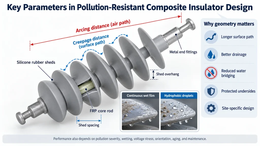
The composite insulator creepage specification guide provides a deeper RFQ framework for salt, dust, and humidity. Final values should follow the governing project method and be confirmed on the released drawing.
Inspection should look beyond visible dirt. Check for tracking, erosion, chalking, punctures, split or missing sheds, exposed core, damaged seals, fitting corrosion, loose hardware, abnormal discharge marks, and changes near grading devices. Compare units in similar exposure zones and record recurring contamination or wetting patterns. Where the maintenance program uses leakage-current, infrared, ultraviolet, or other condition-monitoring methods, interpret results against site history and the utility’s approved criteria.
Cleaning should be condition-based and compatible with the housing material. Aggressive tools, unsuitable chemicals, or uncontrolled high-pressure methods can damage the surface. A hydrophobic-looking surface is not by itself proof of adequate insulation performance, and a temporarily wettable surface does not automatically require replacement. The decision should combine inspection evidence, electrical behavior, material condition, risk level, and the approved maintenance procedure.
A supplier should be able to return a drawing and technical schedule that match the line duty. Ask for the proposed housing material and shed geometry, creepage and arcing distances, core diameter, mechanical rating, end-fitting interface, tolerances, sealing details, grading hardware, inspection plan, and applicable verification records. Require notification and review when materials, molds, fittings, equipment, or processes change.
For a product-level reference, CECI lists a 33kV-70kN silicone rubber composite suspension insulator with hydrophobic silicone rubber sheds for suspension or tension applications. Treat it as a configuration reference, not a substitute for project verification: dimensions, load, voltage duty, fittings, pollution assumptions, and required records must agree with the approved specification.
Composite insulators reduce pollution flashover risk through a combination of silicone-rubber hydrophobicity, suitable shed geometry, and adequate creepage distance. Those features disrupt the wet conductive film and leakage-current path that lead to dry-band arcing. Reliable service still depends on correct site classification, coordinated electrical and mechanical design, controlled manufacturing, sound installation, and condition-based maintenance. The right question is not whether a composite insulator is pollution-proof, but whether a verified configuration manages the site’s contamination and wetting risk with adequate margin.
No. They can reduce risk by limiting continuous wetting and extending the surface path, but severe contamination, unsuitable geometry, aging, damage, or incorrect system design can still lead to flashover.
Its hydrophobic surface tends to form water droplets instead of a continuous conductive film. Actual behavior depends on the compound, surface condition, electrical stress, contamination, and service aging.
Not by itself. Creepage must be evaluated with shed profile, wetting, installation position, air clearance, voltage stress, and the applicable project design method.
Include system voltage, location and pollutant source, wetting pattern, required creepage and arcing distances, mechanical duty, shed and fitting geometry, drawing, quantity, inspection plan, and required test or compliance records.
For an application fit check, contact the CECI technical team with the line voltage, contamination and wetting description, installation position, creepage and arcing requirements, mechanical load, fitting interface, drawing, quantity, and documentation expectations.

 Room 1502, NO.12, Shangwu Waihuan Road, CBD, Zhengzhou, China
 +86-18937178812
 sales@gridinsulators.com


 October 29, 2026
