what are you looking for?

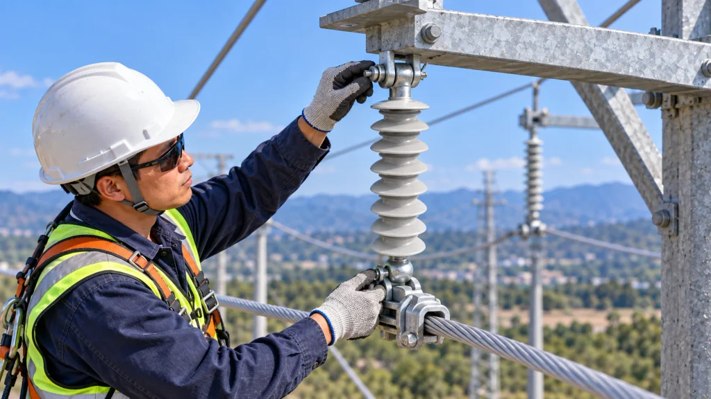
Polymer insulators can be damaged before a line is energized, even when the defect is not visible from the ground. Premature failure often begins with a mismatch between the ordered configuration and the line, rough handling, unintended lifting loads, incorrect fitting alignment, or an incomplete inspection. The objective is to protect the mechanical load path, preserve the housing and seals, and verify that the assembly matches the project specification.
A polymer composite insulator is a complete assembly rather than a stand-alone plastic part. A typical design combines an insulating housing, fiberglass-reinforced core rod, and metal end fittings. The housing provides the insulation surface while the core and fittings transfer mechanical loads. Damage at an interface can remain hidden until tension, bending, vibration, contamination, wetting, or electrical stress is applied.
CECI lists polymer composite insulators for pin, suspension, line-post, and related power-line configurations. A visually similar unit is not automatically interchangeable: voltage, mechanical requirement, connection geometry, creepage, arcing distance, installation position, and surrounding hardware must agree before field work starts.
The first mistake happens before the crew reaches the structure: ordering by a general description or by voltage alone. Pin, suspension, and line-post assemblies can have different load directions, fittings, lengths, and mounting interfaces. Confirm the model, drawing, orientation, mechanical rating, creepage, arcing distance, and connected hardware. If a dimension is missing, obtain configuration-specific confirmation rather than adapting the part in the field.
Light weight does not mean unlimited handling tolerance. Dragging, dropping, or bending a long assembly can cut the housing, chip a shed, stress the core rod, or disturb an end-fitting interface. Support the unit at the points specified by the supplier or procedure, use clean lifting accessories, prevent sharp-edge contact, and keep it off the ground. Record any impact, scrape, crack, or unusual deflection for review before installation.
During lifting and stringing, the assembly can experience side loads, bending, torsion, or impact that are absent from normal operation. Pulling on the housing, using it as a handhold, or allowing a long unit to sag can transfer force into the core or fittings. Plan the lifting route, use enough people or approved equipment, and keep the assembly in its installation orientation. Never use it as a lever, step, tie point, or brace.
Incorrect tightening can damage threads, distort a fitting, crush an interface, or create an off-center load path. Under-tightening allows movement; over-tightening introduces local stress. Use the project or supplier procedure for fastener grade, sequence, torque, locking method, and inspection. Do not borrow a torque value from another fitting or material. Check that pins, clevises, eyes, clamps, and brackets are seated and aligned before tensioning the conductor or jumper.
An insulator and its adjacent hardware work as a system. Mixing a new composite unit with an old clamp, pin, bolt, or yoke can create mismatch, eccentric loading, corrosion concerns, or an unsuitable connection direction. Compare interface dimensions, load rating, material, surface treatment, clearances, and locking features. Drilling, grinding, welding, or reshaping a fitting changes the qualified configuration and requires engineering approval.
An installation can be mechanically sound and still be electrically unsuitable. Salt fog, industrial dust, humidity, desert dust, altitude, wind-driven deposits, and wetting affect surface leakage and flashover risk. Verify creepage, arcing distance, shed profile, phase-to-ground clearance, and phase-to-phase clearance for the actual site. A longer catalog dimension alone does not prove adequate performance; follow the governing standard and the asset owner’s pollution criteria.
Concrete dust, metal filings, grease, uncured coatings, sharp tie wire, and damaged packaging can affect the housing or create a local electrical stress point. Keep sheds and interfaces clean, remove temporary protection only when ready to install, and inspect the housing, end seals, and fitting junctions. Do not use solvents, abrasives, or repair compounds unless permitted by the product documentation. A repair that changes the surface or seal is a technical deviation, not a cosmetic fix.
A crew may complete the physical work correctly yet leave no evidence that the right configuration was installed. Record the model or drawing, structure or pole, orientation, fitting details, tightening verification, clearances, conditions, and photographs before energization. For a new design or changed fitting, material, or process, a first-article or representative-unit review can confirm that dimensions, interfaces, and manufacturing details match the approved configuration before batch release.
A pre-energization check should connect the installed unit to the approved design, not just confirm that it is present. Compare the nameplate or model with the work pack, verify the fitting chain, and inspect the housing and seals under good lighting. The checklist below is a practical minimum; project standards and asset-owner procedures may require more tests or hold points.
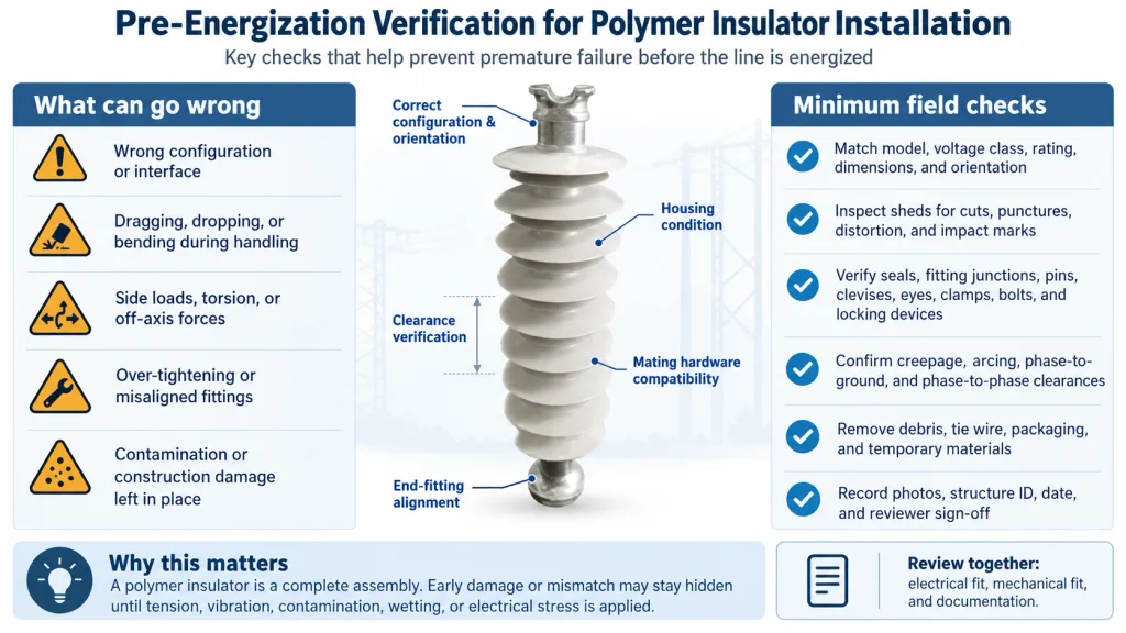
1. Confirm the model, voltage class, mechanical rating, dimensions, end-fitting type, and orientation.
2. Check for cuts, punctures, missing or distorted sheds, exposed fibers, cracks, seal gaps, and impact marks.
3. Verify that pins, clevises, eyes, clamps, bolts, locking devices, and brackets are fully seated and aligned.
4. Measure or confirm creepage, arcing, phase-to-ground, and phase-to-phase clearances against the approved design.
5. Remove temporary tools, tie wires, packaging, debris, and unauthorized protective materials from the assembly.
6. Capture photographs and sign-off records that identify the structure, configuration, inspection date, and responsible reviewer.
Installation lessons should be converted into procurement fields instead of remaining as informal crew knowledge. CECI’s polymer composite insulator range can be reviewed through the polymer composite insulator category, but the correct replacement or new-build unit still depends on the project specification and verified conditions.
Include the application, system voltage, mechanical load, installation position, connection geometry, required length, creepage and arcing distances, pollution conditions, conductor or jumper arrangement, and mating hardware. Add photographs, drawings, measured dimensions, and the reason for replacement. If the previous unit was damaged during handling or assembly, describe the event so the supplier can review protection, packaging, lifting points, or installation controls.
Ask for the drawing and identification of the quoted configuration, applicable material information, dimensional records, routine inspection evidence, and the project or utility documents that govern acceptance. A family-level description is not proof that every fitting combination has been evaluated. For production control, the first-article inspection guide explains why the representative unit should be checked before repeat production, especially after changes to materials, tooling, equipment, or process.
Most installation-related polymer insulator failures are not caused by one dramatic event. They can begin with a mismatch, side load, damaged seal, incorrect fitting, or missing record. Preventive work is a chain: select the configuration, handle it with controlled support, assemble hardware without guessing, verify the electrical geometry, and document the condition before energization. If a failure has already occurred, use evidence rather than appearance alone; the composite insulator failure-modes guide can help separate diagnostic questions from installation-prevention questions. For a technical fit check or quotation, contact CECI’s technical team with the model, drawings, dimensions, operating conditions, photographs, and required quantity.
Do not assume that a small bend is harmless. The permitted handling and installation loads depend on the design and procedure. If the unit has been bent, dropped, or used to support another component, record the event and request a technical disposition before energization.
No. Voltage is only one input. Mechanical rating, creepage, arcing distance, end-fitting geometry, installation position, clearances, pollution conditions, dimensions, and the connected hardware must also match the approved design.
Look for cuts, punctures, missing or distorted sheds, surface contamination, erosion, exposed fibers, cracks, seal gaps, and marks that suggest impact or discharge. Inspect the full circumference and the transition to each metal fitting, not only the most visible side.
A decision should follow the asset owner’s safety procedure and an engineering assessment. Core exposure, suspected mechanical-load loss, severe fitting movement, deep housing damage, active electrical deterioration, or an unknown impact history generally warrants prompt escalation rather than an informal field repair.
Send the model or drawing, voltage, mechanical requirement, dimensions, end-fitting configuration, application, operating environment, installation position, damage photographs, inspection findings, quantity, and applicable standards. This gives the supplier enough context to review fit instead of matching a name alone.

 Room 1502, NO.12, Shangwu Waihuan Road, CBD, Zhengzhou, China
 +86-18937178812
 sales@gridinsulators.com


 November 12, 2026
